Very high energy cosmic gamma rays
Very high energy cosmic gamma rays are photons of light that carry precious information on violent non-thermal phenomena in the Universe, such as the galactic supernova explosions or the environment of the super-massive black holes in the cores of galaxies. They can also be used for the inquiries about fundamental physics questions, such as the nature of the dark matter. Being neutral, gamma rays are not deflected by magnetic fields in our Milky Way and beyond it and, while arriving to the Earth, point back to the sites of their production. At these high energies, gamma rays from even the strongest sources – for example, the famous Crab Nebula – are very rare (≤ 1/1000) compared to the high energy cosmic particles (protons and heavier nuclei).
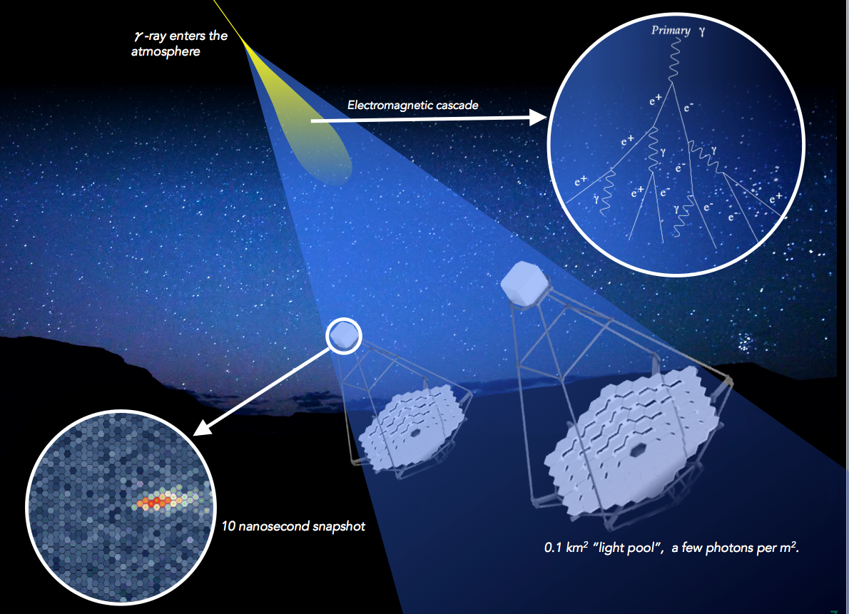
The fluxes of VHE gamma rays rapidly decrease with energy, so the observation rate with small spacecraft-based detectors, for example Fermi LAT, quickly becomes too low. For very high energies a much larger detector is needed, so the Earth's atmosphere is used as the detection volume. Incoming VHE gamma rays interact with nuclei of atmospheric gases in upper layers of the atmosphere and create extended air showers (EAS) of relativistic particles. These are accompanied by rapid (~10 ns long) flashes of blueish Cherenkov light, which can be used for indirect detection of the VHE gamma rays.
Arrays of imaging atmospheric Cherenkov telescopes (IACTs) on the ground collect this light using pixelated cameras of photomultipliers in the focal plane of optical mirror systems. In the last decade the ground-based gamma-ray astronomy achieved spectacular results (through current experiemnts MAGIC, H.E.S.S. and VERITAS), having discovered and studied more than 150 galactic and extra-galactic VHE gamma-ray sources and sheding light on processes of particle acceleration in these sources, absorption of gamma rays from distant galaxies and other fundamental open questions.
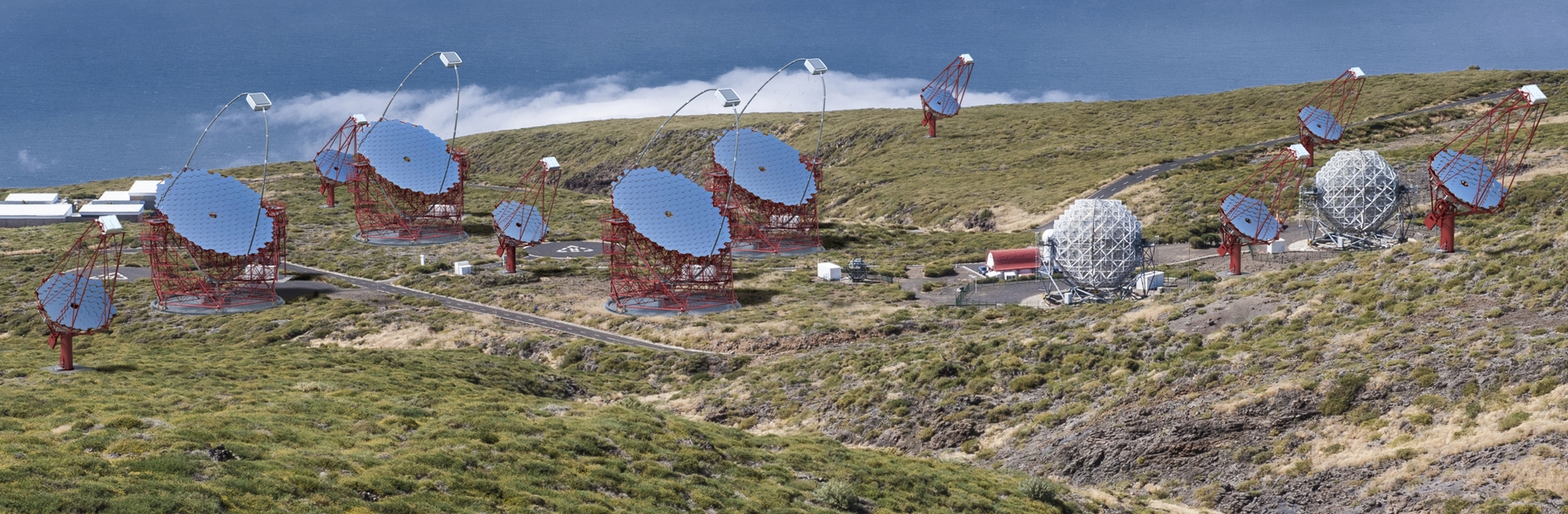
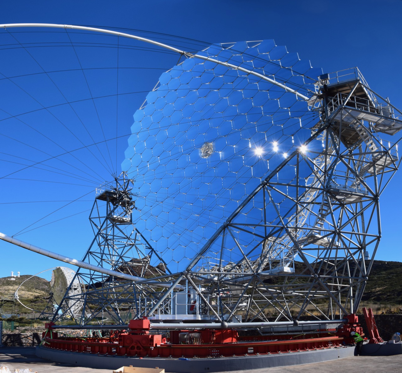
Cherenkov Telescope Array Observatory (CTAO) is a new generation IACT with design sensitivity improved by at least an order of magnitude compared to existing instruments and extended energy coverage. The CTAO North site is at the Roque de los Muchachos astronomical observatory on the island of La Palma, Spain, where the first Cherenkov telescope LST-1 is already in place.
CTAO, which is expected to discover more than 1000 new VHE gamma ray sources over the entire sky, will seek to address a wide range of questions in astrophysics and fundamental physics that fall under three major study themes: understanding the origin and role of relativistic cosmic particles, probing extreme environments and exploring frontiers in physics.
Since the atmosphere is used as the CTAO calorimeter, continuous atmospheric monitoring up to the height of about 15km, where the EAS begin, and the understanding of atmospheric processes is of paramount importance for CTAO operation and the achievement of its science goals. The task requires the use of a remote-sensing instrument (Raman lidar).
Remote sensing of atmospheric properties
Remote sensing measurements are based on the detection of forward- or backscattered acoustic or electromagnetic signals. The advantage of these methods compared to traditional ones is the ability to obtain 3D fields of observables as well as better spatial and temporal resolution of the data. Their main problem is the correlation between the measured signal and atmospheric properties, which are not related in a straight- forward fashion as in case of traditional in-situ measurements. According to the type of signals, we distinguish three types of remote sensing (RS) systems:
- SODAR (SOund Detecting And Ranging) – uses acoustic waves (wavelengths from 10 cm – 100 m),
- RADAR (RAdio Detecting And Ranging) – uses electromagnetic waves (wave- lengths from 1 mm – 10 m),
- LIDAR (LIght Detecting And Ranging) – uses electromagnetic waves in ultravio- let (UV), visible (VIS) or near infrared (IR) range (wavelengths from 0.1 – 11 μm).
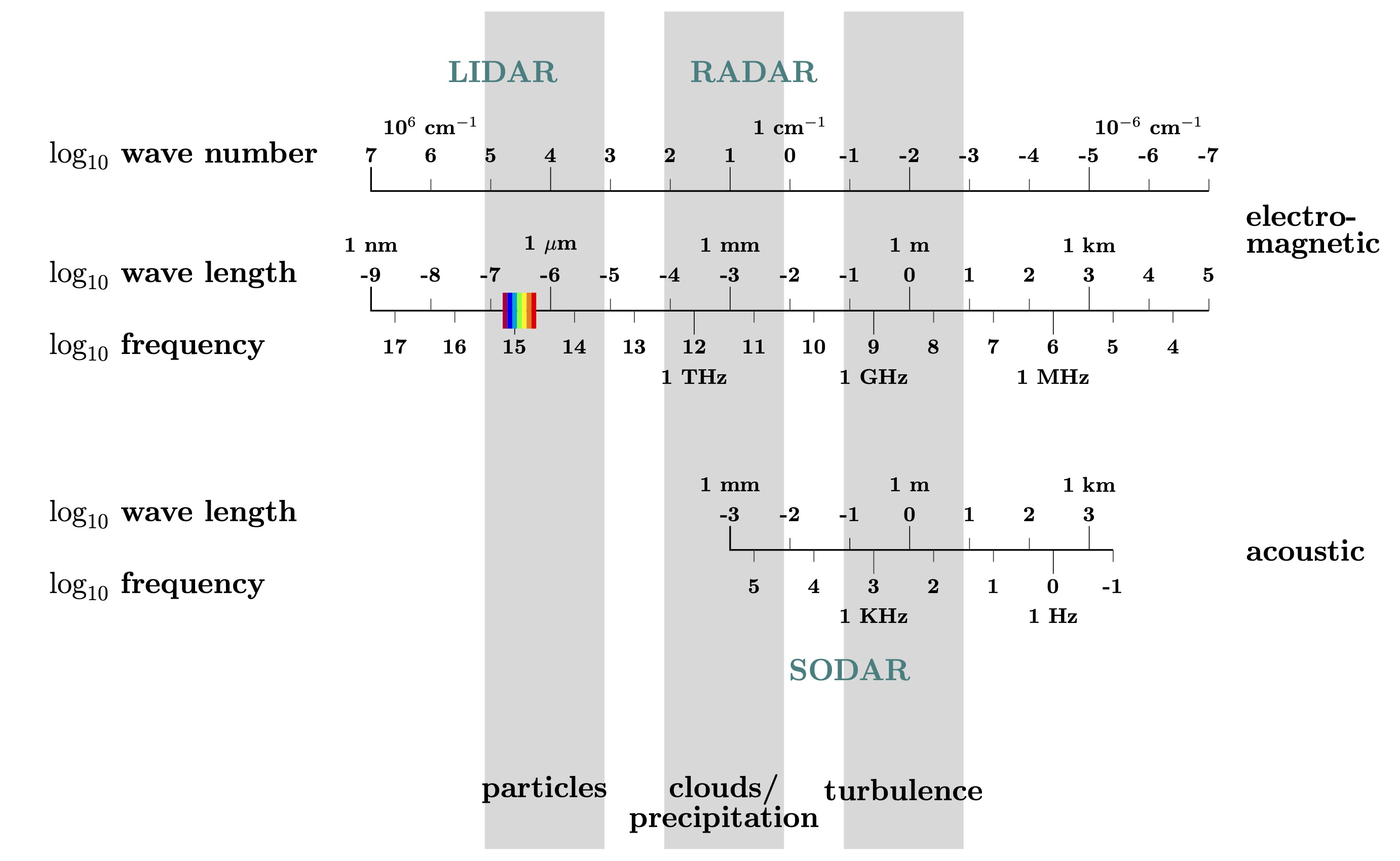
Different signal wavelengths determine the structures that can be observed by the corresponding RS systems. SODAR systems detect the thermal inhomogeneities, RADAR systems the raindrops and layering of the atmosphere, while lidar systems detect small particles and molecules.
Wavelengths used in lidar systems are from the UV, VIS and IR part of electromagnetic spectrum. The wavelength used depends on the type of scattering we would like to observe – the scattering on particles (Mie scattering) or on molecules (Rayleigh scattering and Raman scattering).
Lidar measurements
Lidar measurements are based on the detection of light
backscattered from molecules and aerosols in the air. A
lidar device consists of a transmitter – strong light source
capable of emitting either continuous wave or short high
energy pulses of light, and receiver – an optical system and
photomultiplier or avalanche photodiode to collect the
backscattered light and convert to an electric signal.
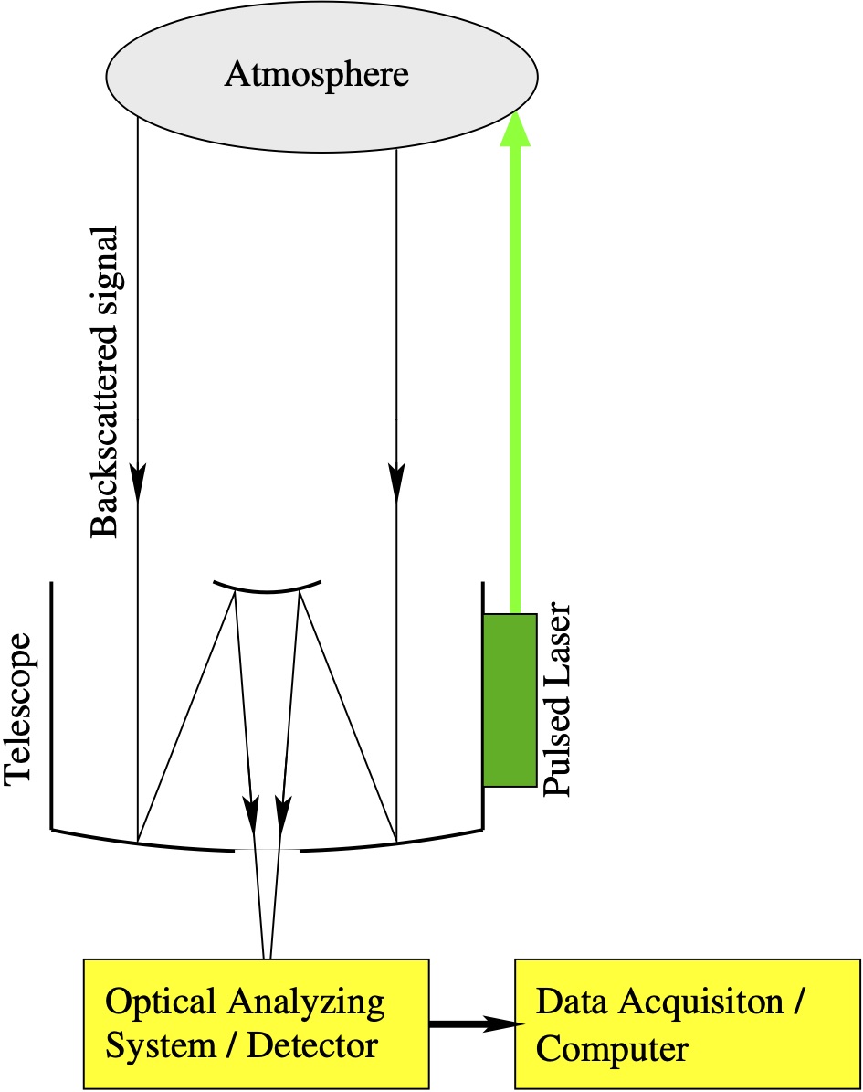
The pulsed laser signal transmitted into the atmosphere
by our lidar system is scattered in all directions by
molecules and aerosols. A small portion of the signal is
scattered back to the receiver, where the photons are
collected by the telescope and then analyzed by an optical
system, which selects specific wavelengths from the received
signal. Selected photons are then detected by a
photon-sensitive device and converted into an electrical
signal. The distance between the observed structure and the
transmitter is determined by the time delay between the
emitted and the return signal. The return signal has to be
corrected for the energy variation of the laser output and
the inverse-range square decrease in signal.
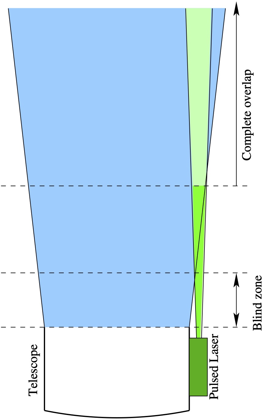
Mechanically, the transmitter-receiver configuration can either be bi-axial or co-axial. In bi-axial configuration the transmitter and receiver axis are separated, which results in a blind zone in the near range, while in co-axial configuration the axis of transmitter and receiver coincide, resulting in shorter blind zone, but the return signal of such a system often gets saturated at near ranges. The bi-axial systems mostly work in the full overlap region where the overlap function is well defined. Signal saturation does not occur due to blind zone in the near range.
The CTAO North Raman Lidar Pathfinder consists of an Nd:YAG pulsed laser as a transmitter, a large collecting mirror as receiver, photomultipliers as a detectors, and a digitizers (transient recorders) for conversion of analog signal into digital form, which is then stored by custom-made data acquisition software. The Quantel Brilliant Nd:YAG laser operates at wavelengths of 355, 532 and 1064 nm, pulse energy of 250 mJ and pulse length of 5 ns and has a 10 Hz repetition rate. The backscattered light from laser pulses is received by a collecting mirror with an area of 2.5m2 and transformed from photons to electrons by photomultipliers. Finally the signals pass to the digitizers, which enables data sampling with a spatial resolution of 3.75 m. Each lidar measurement is an average over 500 laser pulses recorded in 50 s. The range of the lidar system is approximately 50 km under clear weather conditions.